
What Does Second Gear Start Mean on My Dash
MODIFY YOUR GM Machine
FOR WINTER DRIVING 
Adding SECOND GEAR START WITH GEAR INDICATOR to your GM car
DISCLAIMER
This information is provided for but the purpose of increasing rubber in winter driving.
This device is not guaranteed to forbid wheel skid.
The page writer will not be responsible for any damages caused by any of the following:
- Bad connections, incorrect connections, or sloppy wiring methods
- Any commutation of improper parts
- Attempts to utilise this data for auto racing purposes
- Attempts to use this data for cars not made by GM
- Whatsoever lit check engine light resulting in vehicle service charges
- A driver overloading the engine, transmission, or drive train
- Law Enforcement thinking the Indicator is a RADAR or LIDAR detector and ripping information technology out
- The voiding of any warranties that installing this device may crusade
- Whatsoever traffic blow or missed engagement acquired past failure to negotiate slippery conditions
- Annihilation else, including fabric from this folio copied to other sites.
One of the reasons that modern vehicles accept so much trouble in winter atmospheric condition is that the engines are so powerful that they easily cause the wheels of the automobile to spin on snow or water ice. The high torque multiplication of commencement gear contributes to this.
The Second Gear Start modification will not totally foreclose wheel slip. The commuter'south skill and the slipperiness of the surface are also factors in wheel slip. Simply this device will greatly help the driver to control wheel slip.
Unlike devices in other websites that propose using such wiring, this has been tested in a 2002 Pontiac Bonneville SLE endemic by the folio author, and has been shown to activate the transmission as described.
This should work in any GM-designed auto with a four-speed automatic manual fabricated since 1994 and controlled past the GM Powertrain Control Module (PCM).
This has not been designed for cars made by other companies and sold in the US by GM.
This has not been designed or approved in any manner past GM. It is in no way connected with GM or its subsidiaries.
The instructions for using this device are given first, followed by the theory of performance, and so the construction details.
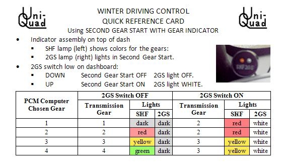
USING SECOND GEAR Get-go WITH GEAR INDICATOR
Second Gear Get-go indicator (top)
Second Gear First control (red switch)

Indicator module
Here is how to employ Second Gear Start With Gear Indicator:
- This unit has 2 components on the instrument panel:
- The SHF/2GS indicator assembly on the dash top (circular object at very top of photo)
- The reddish 2GS switch low on the dashboard (bottom correct of photo)
- The indicator associates has 2 lamps:
- The left SHF lamp shows the following colors for the gears when the Gearshift is in whatsoever forward gear:
- 1st Gear: Nighttime
- 2d Gear: Carmine
- 3rd Gear: Xanthous (or Bister)
- fourth Gear: GREEN
- Note that a small delay occurs betwixt when the Powertrain Command Module (PCM) selects the shift (the lite changes color)
and when the hydraulics in the transmission really make the shift.
- The right 2GS lamp lights WHITE when the 2d Gear Start (2GS) switch is activated.
- The left SHF lamp shows the following colors for the gears when the Gearshift is in whatsoever forward gear:
- The 2GS switch has two positions:
- Printing the bottom of the switch to turn OFF Second Gear Kickoff for normal driving.
The 2GS low-cal will be OFF. - Press the summit of the switch to plough ON Second Gear Commencement for slippery atmospheric condition.
The 2GS light will exist WHITE.
- Printing the bottom of the switch to turn OFF Second Gear Kickoff for normal driving.
- Operation test:
- Brand sure the Gearshift is in Park and that the Ignition is OFF.
- Plow ON the 2GS switch.
- Plow the Ignition to ON, but practice non beginning the engine.
- The left light (SHF) should be YELLOW* and the right light (2GS) should be WHITE (see photo).
- Offset the engine. The SHF low-cal should turn RED*.
- Turn OFF the 2GS switch. Both lights volition become OFF*.
- If yous are not going to drive the motorcar, turn OFF the Ignition.
- Normal Driving:
- Leave the 2GS switch OFF.
- Use the SHF light to help you save gasoline. Through throttle control, you can cause earlier shifts to higher gears.
- Icy or Other Slippery Conditions:
- Leave the 2GS switch OFF until it is needed.
- Plough the 2GS switch ON when the streets are slippery plenty that control is impaired.
- If the car has traction control, it can interfere with the using Second Gear Commencement to increase traction. Plough OFF Traction Command if information technology interferes.
- Do not look quick dispatch when the 2GS switch is ON. Accelerate gently and drive slow.
- The Check Engine light volition come ON if as well much acceleration is applied.
- If you need quick dispatch, turn OFF the 2GS switch.
- Freeing a car stuck in snow (or other case where the wheel spins):
- Turn Traction Control OFF.
- Turn 2GS ON.
- Use common salt, sand, branches, boards, or other aids to increase traction.
- Alternate between the R and 2 positions on the Gearshift to stone the motorcar out.
- Take it easy. Exercise not overload the engine or manual.
- Freeing a car stuck in a pigsty (or other instance where the bike does not rotate):
- Plow Traction Command OFF.
- Turn 2GS OFF.
- Jack upwards the wheel and fill the hole with boards or other materials to concur upward the wheel.
- Alternately use the R and ane positions on the Gearshift to rock the car out.
- Take it easy. Practice not overload the engine or transmission.
- Stopping a car with brake failure:
Many people practice non know how to cease a car without brakes. It's easy if yous know how.- Have your foot off the gas.
- Effort the parking brake first.
- Do NOT Turn OFF the Ignition, or the transmission will shift into neutral.
- Plough 2GS OFF.
- Move the Gearshift to 3, so to 2, and and then to 1 as the motorcar slows downwardly.
- Steer uphill.
- When the automobile fully stops, move the Gearshift to Park.
- Turn OFF the Ignition.
- Call for a tow.
- Other tips for using 2nd Gear Kickoff With Gear Indicator:
- Print out and keep the Quick Reference Card (below).
- Turning ON the 2GS switch can affect engine braking.
- For increased engine braking, motility the Gearshift to the 3 or ii position.
- Do not endeavour to strength a quick acceleration when the 2GS switch is ON. Excessive forcefulness can impairment the transmission.
- If you need quick acceleration, plow OFF the 2GS switch.
- Notation that, unless the relay (below) is installed, the 2GS switch as well prevents the transmission from using 4th gear. But, since 4th gear never engages below 45 mph, and since information technology is not a expert idea to exist going over 45 mph in glace conditions, quaternary gear is not commonly needed when the 2GS switch is ON.
- Also annotation that, unless the relay is installed, the SHF light will always be Crimson or Xanthous with 2GS ON.
- Note that turning the 2GS switch ON will shift the transmission into 2nd gear when the Gearshift is in the 1 position.
A Discussion OF Alert
It has come up to the attending of the page author that some constabulary enforcement officials mistake devices such as this one for illegal RADAR or LIDAR detectors. Instead of realizing that in that location are other legal modifications people can make to their cars, they wrongly presume that any device such as the Indicator Assembly is an attempt to disguise an illegal detector.
States with such backward laws include Virginia, the Commune of Columbia, and Quebec.
It might be a good idea to print the Quick Reference Card to a higher place and keep information technology in the machine as testify that this is not an illegal detecting device.
WHY THE Page AUTHOR BUILT THIS
The following events resulted in the folio author edifice this device:
- The previous ii cars the page writer endemic had some course of Second Gear Kickoff.
- Second Gear Outset worked quite well with slippery conditions on the other 2 cars.
- One fourth dimension, the folio author was caught in an ice storm where almost all of the cars slid off the street into curbs and ditches. With Second Gear Offset and antilock brakes, the folio author however had complete command of the motorcar. Just he did turn onto a quieter street to avoid beingness hit by other cars.
- The urban center relocated the page author'due south driveway to add curbs and sidewalks on the street.
- The new driveway has a sharp uphill section just before the ridge preventing street drainage into the driveway.
- The page author agreed to the pattern of the driveway because his car had 2nd Gear Start.
- The President'due south Cash for Clunkers programme depleted the market of cars with 2d Gear Start.
- The folio author had to speedily buy a automobile because of the sudden loss of utilise of the previous car.
- The new machine couldn't go out of the driveway on days when ice storms happened.
- Due to financial agreements, the page writer would take lost a lot of money if he traded the car at the fourth dimension he modified it.
- The page author decided to research adding Second Gear Start to the car.
- The author added gear indications for saving gas when he discovered how easy it is to do.
THEORY OF Functioning FOR Winter DRIVING
The theory of the functioning of this device is based on the principle of the weakest link in a concatenation. But instead of a chain, there is a drive railroad train with two places where slippage can occur. Which one slips depends on the amount of torque needed to brand each 1 sideslip.
Known values for the 4T65 transmission:
- The gear ratios are every bit follows:
1st Gear 2nd Gear 3rd Gear 4th Gear Reverse: ii.921:one 1.586:one 1.000:1 0.705:1 -2.385:1
Let's presume the following:
- Allow the value n be the amount of input torque on the torque converter needed to make it skid.
- V times northward is the corporeality of output shaft torque needed to make a wheel sideslip on sample ice (Low).
- Four times n is the output shaft torque needed to make a wheel skid on more than slippery water ice (High).
- Torque multiplication by the torque converter (TC) just before information technology slips is 2:one.
Now look at the tabular array of operation of this transmission:
| Gear | TC Slip Torque | TC Ratio | Gear Ratio | Output Ratio TC & Gear | Output Shaft Slip Torque Depression | High | Engine Torque To Slip TC | Engine Torque To Slip wheel Depression | High | Which Will Slip First Low | High |
|---|---|---|---|---|---|---|---|---|
| i | n | 2 | 2.921 | 5.842 | 5n | 4n | northward | 0.856n | 0.685n | wheel | bike |
| ii | n | 2 | ane.568 | 3.136 | 5n | 4n | n | i.594n | 1.276n | TC | TC |
| 3 | n | 2 | 1.000 | 2.000 | 5n | 4n | north | .2.500n | 2.000n | TC | TC |
| 4 | north | 2 | 0.705 | one.410 | 5n | 4n | n | .three.546n | 2.837n | TC | TC |
| R | n | 2 | 2.385 | four.770 | 5n | 4n | n | .one.048n | 0.839n | TC (?) | wheel |
The idea here is to make the torque converter (TC) the weakest link in the concatenation. It will slip first, before the road wheels do, if the engine torque needed to skid a wheel is larger than n. Find that in the table, the engine torque needed to sideslip a wheel is greater than n in all gears except starting time gear (and reverse, if the ice is very slippery).
The way to do this is to commencement the car moving in 2nd gear. This way, the road wheels are much less likely to slip nether dispatch. Just you must take it slow and piece of cake to realize this do good.
Annotation that slow and careful driving is too needed here to preclude damage. You tin't drive at normal speeds or acceleration rates, or yous can heat up the transmission or strain certain parts of the drive train. Your Check Engine light will come up ON if y'all are overdoing it.
I problem with the other devices seen in various websites is the tendency of such devices to crusade the Check Engine light to come ON. This device will non cause the Bank check Engine lite to come ON unless the driver is abusing the engine or drivetrain.
THEORY OF SAVING GAS WITH THE SHF INDICATOR
Here is a tabular array of the SHF indications and gas mileages for each gear:
| Gear Used | SHF Color | Gear Ratio | Steady Speed MPG |
|---|---|---|---|
| ane | Nighttime | two.921:1 | 7.24 |
| 2 | Cherry-red | 1.568:1 | 13.v |
| 3 | Yellow | one.000:1 | 21.2 |
| 4 | Light-green | 0.705:1 | thirty.0 |
MPG figures are based on a highway gas mileage of 30.0 MPG.
Gear ratios are for 4T65 transmission.
The driver uses the SHF indicator and throttle control to get into the highest gear bachelor equally before long as possible.
Note that the transmission will not shift into 4th gear until the car is going in the range of 45-50 mph.
THEORY OF OPERATION OF THE CIRCUITRY
-
- Indicating the Gear Selected:
Indicator lonely
- Each gear solenoid has an impedance below 100 ohms.
- One terminal of each gear solenoid is connected to +12 volts.
- The Powertrain Control Module (PCM) activates a solenoid by grounding its command concluding.
- Each control last (A, B) is at +12 volts with the solenoid OFF, and 0 volts with it ON.
- The light-emitting diode (LED) is wired from the solenoid command terminal to footing.
- The LED lights when the control terminal is at +12 volts, and goes out at 0 volts.
- Thus, the LED lights when its solenoid is OFF.
- The Solenoid A LED is RED, the Solenoid B LED is GREEN. Both are in the aforementioned LED housing.
- Here is a table of the indications:
Gear ratios are for 4T65 manual.Gear Sol
ASol
BRED
LED ALight-green
LED BColour Ratio 1 ON ON OFF OFF Night 2.921:one 2 OFF ON ON OFF Ruby i.568:1 3 OFF OFF ON ON Yellow one.000:1 4 ON OFF OFF ON GREEN 0.705:ane - The resistance in each LED circuit is loftier enough that the solenoid volition not be activated by the current flow needed to lite up the LED.
- Note that there is a filibuster between the fourth dimension the PCM requests a shift (and the light changes colour) and the time the shift actually takes place. The hydraulics carefully fourth dimension the shift to make information technology smooth.
-
- Controlling Which Gear is Selected:
The basic 2GS controller
- Solenoid A is activated in 1st gear and 4th gear.
- This modification inserts a switch into the wire connecting the Powertrain Control Module and Solenoid A (also labeled the 1-2 solenoid) in the transmission.
- When the switch is closed, the transmission functions normally.
- When the switch is open up, the manual will not shift into 1st gear or 4th gear. This causes the transmission to start the car moving in 2nd gear, and allows it to shift into tertiary gear.
- This would work if the PCM did non report trouble when information technology notices the absenteeism of the solenoid. In many models, the cheque engine light comes ON after the switch is opened.
- The side by side part deals with preventing the problem study:
Preventing the PCM from Reporting Trouble:- If the PCM notices that Solenoid A is missing, it issues a trouble lawmaking, and the Check Engine light comes ON.
- The trick is to make the PCM think the solenoid is present, even when information technology really is not present.
- Using a double-throw switch allows the switch to substitute a dummy load for the solenoid curlicue in the circuit.
- A 100-ohm ii watt resistor does the job. Information technology pulls the voltage on the control pivot up to 12 volts when the PCM is not using the solenoid. This is plenty to make the PCM see the correct voltage on the output.
-
- Allowing 4th Gear when 2GS is ON:
2GS with 4th gear
- As presented in a higher place, the excursion disables both 1st gear and quaternary gear.
- This is non usually a problem, because 4th gear engages only at speeds above 40 mph. A car would not normally be driven above xl mph in slippery conditions.
- If 4th gear is really needed, a grand-ohm 12 V single-pole double-throw relay can used.
- The relay curl is continued from the Solenoid B (2-3) control final to ground.
- The relay contacts substitute the relay coil for the resistor when the PCM wants tertiary gear or quaternary gear.
- Here is a table of gear selections with and without the relay:
PCM
GearPCM
APCM
B2GS
OFF2GS ON
No Relay2GS ON
& RelayRelay
Curl1 ON ON 1 two ii OFF two OFF ON 2 two 2 OFF 3 OFF OFF 3 3 3 ON 4 ON OFF 4 three 4 ON - The relay enables Solenoid A (1-two) whenever Solenoid B (2-3) is non energized.
- A 100-ohm two watt resistor does the chore.
-
- Combining the Circuits:
Combined 2GS and Indicators
This circuit combines Second Gear Start with the Gear Indicator Assembly
This is the version the page author put in his automobile and tested.
- The Gear Indicators are connected to the wires leading to the transmission solenoids.
- The Second Gear Outset wiring goes between the Gear Indicators and the PCM. Just some of the wires are shared by both functions.
- A 2nd LED indicates when 2GS is engaged. A second pole on the switch lights information technology.
- The relay is not used in this version.
- It may be added if desired, but it is not tested.
- The folio author's experience shows the relay is non necessary.
- A 4-wire cable connects the circuit to the transmission. A ground is also required at the instrument console.
- Hither is a table of gear selections and indications with 2GS switch OFF and ON:
PCM
Gear2GS Switch OFF 2GS Switch ON Trans
GearLights Trans
GearLights SHF 2GS SHF 2GS 1 one DARK DARK ii Carmine WHITE two 2 RED Dark 2 RED WHITE 3 3 Yellowish Night 3 Yellow WHITE four 4 Green Night 3 Yellow WHITE
Construction
- A Few Precautions:
- After the engine has been used, the radiator, engine cake, and exhaust parts are hot enough to burn down you. Be careful. It might be a good thought to await until the engine cools down.
- Be careful with the bare portions of wires, especially if they are continued to +12 volts. They might cause some damage if they come in contact with the wrong matter. Be especially careful around the battery terminals.
- Also be careful with wires that you don't know what they are connected to.
- Do not connect two wires together until yous know what both are continued to.
- Beware of precipitous metal parts nether the hood and under the dash. Don't hurt yourself on them, and don't let wires exist cut on them.
- This modification will void any warranty that is however in event on the vehicle.
- Finding Places for the Indicator Panel and Switch Panel:
Indicator and Switch
- Find a place to put the switch. Several possibilities are:
- The folio author used a totally useless prison cell telephone holder on the nuance for a place to put a command console (meet image - crimson switch).
- With a console shift, at that place might be room for the switch near the gearshift. Drilling a hole in the plastic is easy. But cheque what is backside the plastic first.
- Little kits are available for mounting controls under the dash.
- Place the switch where the driver tin easily use it while the car is moving.
- Make sure the switch is not in a identify where information technology will be accidentally bumped.
- If necessary, design and build a case or bezel to put the switch in.
- Find a place for the Indicator Assembly:
- It should exist in a identify where the driver tin look at it without having to move his caput.
- The folio author put it in the corner between the dashboard tiptop and the left roof back up (see image - round object at pinnacle of epitome).
- Make certain the display does non interfere with the commuter's view of traffic.
- Find a place to put the switch. Several possibilities are:
- Finding the Wiring in the Car:
- Detect the transmission command plug. On a 4T65, the plug is on the left side of the transmission at the height. It is virtually the torque converter.
- Find a place under the dash where a wire can be wrapped under a screw continued to the metallic frame of the car for a basis connection. It should exist near the location selected for the 2GS switch.
- Buying the Parts:
You lot volition need the following parts:
- A standard package of flat 4-conductor trailer tail calorie-free cablevision
- At to the lowest degree 6 feet of 4-conductor stranded wire in a round sheath (A)
- A double-pole double-throw rocker, toggle, or slide switch (B)
- One 100 ohm 2 watt resistor (B)
- One 100 K .25 watt resistor (A)
- Ane 2.2 K .25 watt resistor (A)
- One 330 ohm .25 watt resistors (A)
- 2 270 ohm .25 watt resistors (A)
- Three 1N4004 diodes (A)
- One NTE30045 White LED (A, B)
- One XC52RG Reddish/Green bi-colour LED (A)
- Two LED panel mounting rings (A)
- Something to mount the switch on (B)
- A case for the Indicator assembly and a mode to mount it (A)
- Electrical tape
- 1/2-inch underhood conduit
- iii/4-inch underhood conduit
- Liquid tape or insulating blanket
- Cable ties
- Small-scale prototyping excursion board (A if used)
- Estrus shrink tubing to fit the diodes and resistors (A)
- Estrus shrink tubing to fit the LED leads (A)
The items marked (A) are not needed if the Indicator Assembly will not exist installed.
The items marked (B) are not needed if the Second Gear Start Switch volition non exist installed.
You lot will need the following tools:
- Set of screwdrivers
- Set of nutdrivers
- A small-scale soldering iron and solder
- Needle nose pliers
- Diagonal wire cutters
- Wire stripper
- A small saw or a motor tool to cut plastic
- Something nonconducting to fish cables with
- Digital multimeter
- Direct sewing pins
- Building the Indicator Assembly:
Display and switch wiring
Note: if you practise not have electronic construction experience, have someone practise this for you.
- Build the case.
- The folio writer used two onetime prescription pill bottles that fit together well. The small diameter bottle was cut short to fit within the large one, leaving enough of the large one to grade a hood to keep light off the LEDs. Both parts were painted black with Krylon plastic paint.
- Other items, such equally a motion picture can or a small-scale plastic box could be used.
- Drill two one/iv" holes for the LED mounts in the end of the pocket-sized bottle or the forepart of the case used. Make sure the spacing is correct for the distance between the LEDs on the circuit board (if used).
- Drill a hole in the lesser of the large pill bottle or the back of the case used, for the round cable to exit the case.
- If the colors of the wires exercise not match the ones the page author used, make a table to catechumen the colors in this page to the colors in the cables you have.
- Annotation particularly the polarity of several special parts:
- The ring on each diode must point toward the LED.
- The flat on each LED identifies the order of the pins.
- On the NTE30045, the pin nearest the apartment goes to ground.
- On the XC52RG, the pin nearest the flat is the red input. The middle pin goes to basis.
- At that place are ii ways to wire the case:
- Use rut shrink tubing to hold the parts:
- Use the upper diagram at right to help you lot.
- Slip a curt length of modest bore rut shrink tubing over the end of each lead on the LEDs, except the ground lead of the XC52RG. Make certain the ends of the leads protrude.
- Curve little hooks on the ends of all the LED leads, with only enough space for another lead to fit in each claw.
- Bend the basis lead of the NTE30045 and solder information technology to the ground atomic number 82 of the XC52RG, making sure the spacing betwixt the LEDs matches the spacing of the holes in the instance. As well make sure the tubing on the other leads prevents this articulation from touching the other leads.
- Cut all of the leads of all of the diodes and resistors except the 100-ohm resistor to a length of 1/iv inch and bend them into tiny hooks.
- Make each of the following connexion by hooking the hooks together and and then soldering them.
- Solder ane end of the 270-ohm resistor to the lead for the scarlet LED of the XC52RG.
- Solder one end of the 330-ohm resistor to the free cease of the 270-ohms resistor.
- Solder one end of the 2.2 1000 resistor to the atomic number 82 for the green LED of the XC52RG.
- Solder one stop of the 100 K resistor to the pb for the white LED of the NTE30045.
- To each of the free ends of the resistors, solder the banded terminate of a 1N4004 diode.
- Cut the large rut shrink tubing into lengths to fit over each chain of components. Sideslip them over the components.
- Strip i inch of sheath off one stop of the round cable. Strip ane/4 inch off each lead.
- Cut iii 1/2-inch pieces of small heat-shrink tubing and identify them over the crimson, green, and white leads.
- Connect and solder the wires of i end of the round cable every bit shown in the diagram.
- Arrange the positions of the pieces of shrink tubing to cover all connections and use the rut of the soldering fe to shrink them.
- Use a circuit board:
- Use the two middle diagrams at correct to help you.
- Cut the circuit board to size, based on the number of holes. Make sure it fits in the case you have chosen.
- Bend the leads of the LEDs as shown, i/4 inch from the case of the LED. Brand certain the flats on the LEDs are to the right when you curve the leads downwards.
- Insert the LEDs into the evidently side excursion board as shown in the diagram.
- Bend the leads of the LEDs so they cover the adjacent 2 pads on the board, every bit shown. The silver parts of the diagram indicate where leads are soldered to pads. Simply do not solder the last pad until the other atomic number 82 is inserted.
- Cut off the excess portion of each atomic number 82. Save the cutting ends for later.
- Insert all of the other parts into the board every bit shown in the diagram. Be sure the polarities of the 1N4004 diodes are correct. Bend the leads of each part in the directions shown.
- Solder the leads to the pads they are supposed to overlap and connect to.
- Bend and solder the complimentary ends of the 330-ohm resistor and the 270-ohms resistor together.
- If whatever leads are too short to make the runs of the pads, apply the cut off ends to extend them. Solder them to the board.
- Strip one inch of sheath off one end of the round cable. Strip 1/iv inch off each lead.
- Connect and solder the wires of one end of the round cablevision as shown in the diagram.
- Mountain the LEDs in the two holes in the case.
- Those with ingenuity can devise other mounting and wiring methods. Just be certain they are safe, or you may discover yourself on the route with a blown fuse and an inactive transmission.
- Use rut shrink tubing to hold the parts:
- If any connections tin possibly touch each other, glaze them twice with the insulating blanket.
- Feed the round cablevision out the back stop of the case. If necessary, hold it in place with a cablevision tie.
- Gather the case.
- Build the case.
- Edifice the Switch Console:
Display and switch wiring
The switch console is the bottom drawing in the set of drawings at right.
Use heat-shrink tubing to insulate connections not fabricated at a switch terminal.
- Make the necessary holes in the dashboard or center panel.
- If the switch has a marking when it is thrown in 1 direction, turn that direction up.
- Observe out which terminals on the switch are connected together when the switch handle is thrown downward.
Near switches have the upper sets of terminals connected to the middle set when the switch is thrown to the downward position.
The bottom diagram at right is shown with the dorsum of this kind of switch.
If the switch connects bottom terminals to center terminals with the handle thrown downwardly, wire the switch with the diagram upside down.
- Connect the 100-ohm resistor to the terminals shown in the diagram.
- Connect the wires from the 2 cables to the switch, as in the diagram.
- Solder all of the wires to the switch.
- Connect the black wire from the round cable to the ground screw found earlier.
If necessary, the wire tin be extended by soldering the ends of two wires together and using rut shrink tubing to insulate the joint.
Snaking the Wires:
This is the hardest part of the job.
The folio author got a mechanic to run the apartment cable while the dashboard was disassembled to repair something else.
(This was the only part of the task the page author paid someone else to do.)
- Run the flat 4-wire cable from the switch panel location to the transmission plug. Leave nearly a pes some excess at each end.
Employ one of the post-obit routes:
- Employ 1 of the rubber plugs provided in the firewall for running wires.
- Follow the air conditioning duct through the firewall.
- Go outside through the door frame and so under the car and into the engine compartment.
- Cover the entire portion of the flat cable that is exterior the passenger compartment with the 1/ii-inch conduit.
Leave the conduit not fastened around the cable for the last couple of feet at the end past the transmission until subsequently.
- Run the round cable from the case of the Indicator Assembly at its location to the location of the switch panel.
- Use cable ties to fasten downwards the parts of both cables that are in their final positions.
- Identifying the Wires at the Transmission:
The problem is that the colors of the wires are not standardized betwixt models, and that there are often multiple wires the aforementioned colour.
- Try to become the diagram for the 20-pin plug for your transmission.
- Advisedly cut the tape and remove the plastic conduit. Salve the conduit for later.
- Set the multimeter to a scale of most 20 volts DC.
- Temporarily connect some extra wire from the basis connectedness to the negative lead of the meter. It helps if the meter has alligator prune leads. Run the wire so it volition not interfere with the car being driven.
- Run another length of extra wire from the positive lead of the meter to the manual cable expanse. Connect it to one of the direct sewing pins. Run the wire so it will not interfere with the car existence driven.
- Use the following information to make educated guesses on identifying the wires:
- If you lot have room to disconnect the transmission plug and take the cover off, it makes it easier. Often other parts of the car are in the style without taking several things apart.
- The transmission ability is continued to pivot E. The wire is ofttimes pinkish.
- The one-2 shift solenoid A is connected to pin A. The wire is usually green.
- The 2-three shift solenoid B is continued to pivot B. The wire is commonly yellow, yellowish-blackness, or blackness-white.
- Test the wires in the following manner:
- Shut OFF the ignition. If the manual plug is disconnected, plug information technology back in.
- Push the pin through the insulation of the wire to be tested and then the point comes out the other side.
- Read the meter with the ignition OFF. Information technology will probably read 0 volts. If information technology does non, the wire is the incorrect wire.
- Use the following tabular array to test each probable wire. Impress the table. When driving the auto, have one person bulldoze while another watches the meter. The motorcar should be driven gently. Do each column in lodge, and bank check the meter against the table after each footstep:
C
A
RIgnition
Engine
Gearshift
Motorcar MovementOFF
Stopped
Park
BrakedON
Stopped
Park
BrakedON
Running
Park
BrakedON
Running
Drive
BrakedON
Running
Drive
fifteen mphON
Running
Drive
25 mphW
I
R
Due eastIgn +12 ** 0 V +12 5 * +12 5 * +12 5 +12 V +12 V Sol A 0 5 +12 5 * 0 V * 0 Five +12 V +12 V Sol B 0 5 +12 V * 0 Five * 0 V 0 V +12 5 Sol TCC 0 V +12 Five * +12 5 * +12 V * +12 V * +12 Five * Analog 0 V < 12 V < 12 V < 12 5 < 12 V < 12 5 PCM ‡ 0 V Varying † Varying † Varying † Varying † Varying † Low Ref 0 V 0 V 0 V 0 Five 0 V 0 V Ground 0 V 0 V 0 Five 0 V 0 5 0 V * May differ in some models.
** All 12 volt readings may be as high as xiv volts with the engine running.
† Has an Air-conditioning component. Check with the xx VAC position on the meter.
‡ PCM in this table ways Pulse-Controlled Modulation, not Powertrain Command Module.
- If you think you accept found the +12 Ignition wire, test information technology by connecting the blackness wire in the new flat 4-wire cable to the sewing pin. Turn ON the 2GS switch, then the ignition. If it is the correct wire, the WHITE 2GS lite will be ON when the ignition is ON, whether or not the engine is running, and no matter what gear position the Gearshift is in. If the lite is dim or goes out, the wire tested is the incorrect wire.
- Disconnect the black wire and accept the pivot out of the wire.
- If the wire is the wrong ane, use the insulating coating to seal the holes.
- Make a list of the right wires and their colors. If necessary, mark them.
- Connecting to the Transmission:
Transmission wires spread
Because these connections are exposed to engine vibration, make sure the connections are physically strong by bending hooks in wires and crimping them together before soldering.
- Separate about four inches of the flat cablevision into the private wires.
- Strip 1/iv inch from the free ends of these wires.
- Find once more the wire to Solenoid A.
- Cut the Solenoid A wire in a convenient place
- Strip ane/iv inch from both of the free ends.
- Connect and solder the Solenoid A wire going to the transmission to the green wire in the apartment cable.
- Connect and solder the Solenoid A wire going to the PCM to the white wire in the flat cable.
- Find again the wire to Solenoid B.
- Without cutting the Solenoid B wire, strip 1/4 inch from it at a convenient identify, not lined up with the other connections.
- Connect and solder the yellowish wire in the apartment cable to the Solenoid B wire.
- Find once more the Ignition power wire.
- Without cutting the Ignition power wire, strip 1/4 inch from it in a convenient place non lined up with the other connections.
- Connect and solder the black wire in the flat cable to the Ignition Power wire.
(Notation that the photography rendered the black wire every bit brown. It was left that style then it shows up on the photograph.)
- Glaze all of these connections with the insulating coating, as in the photo. Allow this dry out.
- Coat these connections again. Allow them dry.
- Testing:
Use the post-obit process to exam the connections and the 2GS performance.
If any of these observations (other than those marked with *) requite indications different than the expected indications, cheque the wiring.
- With the engine OFF, 2GS OFF, and the Gearshift in Park, SHF and 2GS LEDs should be OFF.
- Plow the 2GS switch ON. Both LEDs should still be OFF
- Turn Ignition ON. Don't kickoff the engine. SHF should be YELLOW* and 2GS should be WHITE.
- Turn OFF 2GS. The 2GS LED should turn OFF.
- Start the engine. The SHF LED should plough OFF*.
- With the brake on, shift into Reverse. The LEDs should stay OFF*.
- With the restriction on, shift into Neutral. The LEDs should stay OFF*.
- With the restriction on, shift into 1. The LEDs should be OFF.
- With the brake on, shift into 2. The LEDs should stay OFF.
- With the brake on, shift into 3. The LEDs should stay OFF.
- With the brake on, shift into Drive. The LEDs should stay OFF.
- Drive the car. You lot may shift into Reverse if needed to get the car out of the driveway.
- The car should drive normally. If information technology does not, end the examination and get check the wiring.
- Equally you lot bulldoze abroad from a end, SHF should exist OFF at the beginning.
- At a speed well-nigh ten mph, SHF should alter to RED.
- At a speed about 25 mph, SHF should change to Yellowish.
- Drive to a highway. At a speed near 50 mph, SHF should change to Greenish.
- As you slow to a cease, SHF should change to Yellowish, then Reddish, and so OFF.
- Notice a big empty parking lot or a long empty street where you can drive wearisome without blocking traffic.
- From a stop, plough 2GS ON. 2GS should be WHITE and SHF should be RED.
- SLOWLY accelerate. The car should exist difficult to accelerate. Practise Non increase power.
- Somewhere nigh 25 mph, SHF volition turn YELLOW as the transmission shifts into 3rd.
- When SHF is Yellowish, the car handles normally (except not shifting into 4th), until SHF turns RED again when slowing down.
- Plough 2GS OFF. The 2GS LED should go OFF and the car should resume normal operation.
- This ends the examination.
* The SHF LED indications may not match in these Gearshift positions on some models.
- Finishing the Assembly:
Conduit installed
- If whatsoever panels are not fully assembled, finish the assembly now.
- Put the rest of the 1/2-inch conduit on the iv-wire flat cable all the way to the connections.
- Cover the exposed transmission cable with the conduit removed before, or put on new 3/iv-inch conduit.
- If whatever transmission wires remain exposed, utilise some other slice of 3/four-inch conduit to cover them.
- Record all of the conduits in place on the wires with the electrical tape.
- Use wire ties to hold the new conduit in identify. Proceed it away from the exhaust pipes.
- Double check all wiring done nether the hood, to brand certain water tin't become into any connections.
- Use cable ties to secure the under dash wiring.
- Fasten all panels back in identify.
TABLE OF OPERATION
Here is the tabular array of gear selections and indications with 2GS switch OFF and ON:
| NO RELAY | RELAY | ||||||||||||||||||||||||||||||||||||||||||||||||||||||||||||||||||||||||||||||||||||||||||||||||||||||||||||||||||||||||||||||||||||||||||||||||||||||||||||||||||||||||||||||||||||||||||||||||||||||||||||||||||||||||||||||||||||||||||||||||||||||||||||||||||||||||||||||||||||||||
|---|---|---|---|---|---|---|---|---|---|---|---|---|---|---|---|---|---|---|---|---|---|---|---|---|---|---|---|---|---|---|---|---|---|---|---|---|---|---|---|---|---|---|---|---|---|---|---|---|---|---|---|---|---|---|---|---|---|---|---|---|---|---|---|---|---|---|---|---|---|---|---|---|---|---|---|---|---|---|---|---|---|---|---|---|---|---|---|---|---|---|---|---|---|---|---|---|---|---|---|---|---|---|---|---|---|---|---|---|---|---|---|---|---|---|---|---|---|---|---|---|---|---|---|---|---|---|---|---|---|---|---|---|---|---|---|---|---|---|---|---|---|---|---|---|---|---|---|---|---|---|---|---|---|---|---|---|---|---|---|---|---|---|---|---|---|---|---|---|---|---|---|---|---|---|---|---|---|---|---|---|---|---|---|---|---|---|---|---|---|---|---|---|---|---|---|---|---|---|---|---|---|---|---|---|---|---|---|---|---|---|---|---|---|---|---|---|---|---|---|---|---|---|---|---|---|---|---|---|---|---|---|---|---|---|---|---|---|---|---|---|---|---|---|---|---|---|---|---|---|---|---|---|---|---|---|---|---|---|---|---|---|---|---|---|---|---|---|---|---|---|---|---|---|---|---|---|---|---|---|---|---|
|
| ||||||||||||||||||||||||||||||||||||||||||||||||||||||||||||||||||||||||||||||||||||||||||||||||||||||||||||||||||||||||||||||||||||||||||||||||||||||||||||||||||||||||||||||||||||||||||||||||||||||||||||||||||||||||||||||||||||||||||||||||||||||||||||||||||||||||||||||||||||||||
Credits:
I give many thank you to the people who helped me research the design of this project.
- E-Transcontrol gave me the valuable information that finally made this projection work. They actually know what they are doing.
- HP Tuners provided much valuable material.
- Car Talk offered many suggestions.
- Bob Jones Radiator Repair installed the flat cable.
Links:
- Tips for Winter Driving
- Wintertime Driving Gear
- Unusual Traffic Issues and Solutions
DOWNLOAD HERE
What Does Second Gear Start Mean on My Dash UPDATED
Posted by: williamcoles1967.blogspot.com